| Specifications | |
|---|---|
| Power Supply | 6-30 V DC (in either power plug). Or 5 V DC from attached USB cable. |
| Total Power Consumption | ~350 mA (LCD BG Light ON). ~150 mA (LCD BG Light OFF). |
| Fuse | Max. 500 mA Low. |
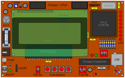
| ATmega Programming | USB drivers to ATmega programmer: »usbasp.2005-11-14.tar.gz« from
http://www.fischl.de/usbasp/. Use AVRdude to upload programs to the chip. |
| CPLD Programming | JTAG (TMS, TDI, TDO, TCK, GND, VCC). Files can be prepared in Xilinx iMPACT and uploaded with a Digilentinc.com JTAG-USB cable and Export. |
| CPLD Clock | 48 MHz. Located at P12. |
| ATmega Clock | 20 MHz. |